 Author: John F. Fletcher, Technical Support Manager
Related Product(s)>>
>>Download Full PDF
Abstract
Time is money and the ability to speed up the process of taking and analyzing coating thickness readings will always pay dividends in reducing inspection costs. Scanning an area of painted steel will always be quicker than taking individual readings but there was always the danger of wearing the probe and reducing its life.
There are now probes fitted with a replaceable wearing surface to protect the probe from abrasion wear when using the probe to scan a surface. Simple plastic caps can be fitted to these probes and the thickness of the cap can be taken in to account in the calibration procedure.
Gauge firmware has also been developed to allow the data generated by the scan to be processed and analysed to produce either an average value for the thickness in the area together with a highest and lowest reading (scan mode), or to produce a batch of individual readings at the rate of 140 reading/minute (auto repeat mode). This firmware is supported by Data Management Software to automate the presentation of the results in reports.
This paper describes the scanning probes and their use and describes how coating thickness data can be collected for analysis using the method described in SSPC PA-2 for determining conformance to dry coating thickness requirements.
INTRODUCTION
The measurement of coating thickness is an important aspect of the inspection process for the acceptance of a coating application on a steel structure. It is not possible to get the correct coating thickness by accident and considerable planning and process control is required to achieve the correct film thickness.
Modern gauge designs have been developed using microprocessor electronics and this has been in part responsible for the achievement of measurement speeds of more than 70 readings per minute using the traditional place and read probes. However, it is now possible to place a probe on the coated surface and take readings while the probe is kept in contact with the surface. These probes are known as scanning probes and have similar functions as the ultrasonic probes used in non-destructive inspection processes. They are available for the single measurement mode application on magnetic substrates (F probes) or the dual purpose ferrous and non-ferrous (FNF probes) for use on both
magnetic substrates and non-magnetic (non-ferrous) metal substrates.
Ferrous probes will measure the thickness of non-magnetic coatings such as paint, plastic, rubber, galvanizing, etc. on magnetic substrates, e.g. steel, magnetic stainless steel, cast iron etc. Non-ferrous probes will measure coatings that do not conduct electricity, such as paint, plastic, rubber anodizing, etc. on non-ferrous metal substrates such as aluminium, some types of stainless steels, copper, brass, etc. These probes are designed to determine the distance between the probe tip and the metal substrate.
COATING THICKNESS MEASUREMENT
For many years electronic coating thickness gauges have been based on a method of measurement where the probe is placed on the coated surface to take the reading. The probe is then removed from the coated surface to a distance which is greater than the maximum range of the probe to reset the gauge ready for the next reading. In the mid 1990ʼs speed of 40+ readings per minute were achieved. By 2011 these speeds had reached 70+ readings per minute using this methodology.
Why is this increase in speed important especially if only a small number of readings need to be taken at any one location?
The measurement speed specification for a gauge indicates how quickly an accurate reading can be taken and therefore how soon subsequent readings can be taken. For example, imagine a job where two inspectors are working on a pipeline measuring the coating thickness, with Inspector 1 on one side of the pipe and Inspector 2 on the opposite side. Both inspectors are required to take a group of 3 measurements every 5 meters according to SSPC PA-2. If Inspector 1 is using a gauge with a measurement rate of 70 readings per minute, and Inspector 2 is using a gauge taking 40 readings per minute, then after five minutes Inspector 1 will be 30 meters ahead of Inspector 2, having completed measurements over 197 meters of pipe. This calculation assumes that the inspectors are able to walk at the same speed along the pipe and take 5 seconds to traverse the 5 meters between measurement sites. Allowing the probe to scan the surface without lifting it between readings would enhance the speed of reading even more.
For a section of pipe 500 m long Inspector 1 will complete the task in 2 ½ minutes but Inspector 2 will take 3 minutes, making Inspector 1 up to 20% faster.
Early in 2013 a new design of probe for either F or FNF applications was introduced. The new probe allows for a ʻsnap onʼ replaceable end cap to be fitted so that the sliding action required to achieve a scan of the whole surface does not cause any wear to the probe tip. This is crucial to maintaining the accuracy of the probe over its life as even relatively soft coatings will cause wear to the tip of the probe which eventually causes changes to the calibration of the probe. A patented offset feature in the gauge ensures that the thickness of the cap is taken account of in the calibration adjustment process and, as the cap wears during use, account is taken of the effect of this wear on measurements. The gauge will also display a warning message when the wear has reached the point where the cap should be replaced.
A trial has been carried out to compare the effect of the speed of reading on the time taken to carry out a sets of coating thickness measurements using a steel test panel that had been blast cleaned and coated with a two-coat epoxy system.
Three sets of measurements were carried out in the Laboratory. The first using the coating thickness gauge with a standard probe for coatings on steel, taking the readings and recording the values by writing them down in a note book. This set of readings is called Batch 1 in table 1 below. The second set of readings was taken using the gauge with the standard probe and recording the values in the memory of the gauge. This batch of readings is called Batch 2. The third set of readings was taken using the gauge with the gauge set to auto-repeat mode and using the new probe in continuous contact with the coating. The readings were recorded in to the memory of the gauge and are called Batch 3 in table 1.
| Table 1 |
|---|
| Batch ID | Description | Reading Rate (Readings/min) | Time (Sec) for 100 Readings | Number of Readings Recorded | Average Thickness (µm) | Lowest Reading (µm) | Highest Reading (µm) |
|---|
| Batch 1 | Written Values | 17 | 395 | 100 | 267.6 | 224 | 282 |
| Batch 2 | Gauge Memory | 77 | 90 | 77 | 255 | 246 | 268 |
| Batch 3 | Scan to Memory | 177 | 60 | 177 | 245 | 202 | 486 |
This data shows that the scan mode is 10 times faster than the traditional written recording method and approximately 2.3 times the rate for the standard probe when the readings are recorded to the memory of the gauge. The gauge memory method is 4.5 times faster than the traditional method and given that the gauge reading rate is the same for both these methods, the difference is the time taken to note down the value on paper. Each reading using the traditional method takes ~3.5 seconds to complete.
It is expected that in the field this time will be significantly longer as holding a note book and pen along with the probe and gauge makes this awkward to do on site.
THE LATEST COATING THICKNESS GAUGE DESIGN
The current design of Coating Thickness Gauge has evolved from the early hand-held electronic coating thickness gauges first made available in the 1980ʼs. However, new designs include features that improve the suitability of the gauges for use in the field by making them more rugged, for example including a water-resistant case. The gauges are also more powerful and easier to use than earlier designs due to the enhanced power of the microprocessors at the heart of the electronic design.
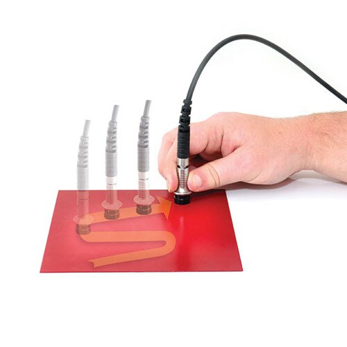
The New Ultra/Scan Probe in Use
In the case of the new probe, the gauge firmware, in the patented Top (T) version, has been enhanced to allow this probe to operate in several modes for swift data collection in to the memory of the gauge. In the first mode the probe can slide over the surface of the coating and, as the probe is lifted, the gauge displays the average coating thickness value for the area, the highest thickness value and the lowest thickness value. The summary for each set of readings, generated when the probe is lifted, can be displayed (average, high and low) on a run chart and stored in the memory of the gauge.
Alternatively a reading rate in excess of 140 readings per minute can be achieved in an operating mode that allows a reading be taken and stored approximately every half second as the probe slides across the surface, with each individual reading stored in the memory of the gauge. This will significantly speed up the inspection of large areas of coating.
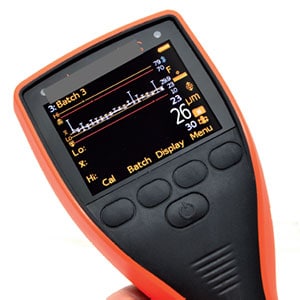
The Run Chart Display
The firmware also has a Counted Average function and this can be used with the scanning probe to set a fixed number of readings in each area or spot and the average of these individual groups of readings is then stored in the memory of the gauge.
Using a Fixed Batch Size allows the maximum number of readings to be defined by the User for each batch. Once this number of readings have been collected and stored, the gauge automatically closes the batch and opens a new batch linked to the previous batch, (e.g. name-1, name-2, etc.).
Job specifications for coating thickness determination often describe the number of individual thickness gauge readings to be taken as a spot measurement and the number of spot measurements for a given area. For example, SSPC PA-2 requires three gauge readings per spot and five spot readings in a 10 m² (~100 ft²) area.
With the new probe and the Auto Repeat function, data that is compliant with the SSPC PA-2 method can be collected for a given area more than 40% faster than with the more traditional measurement method. A counted average setting of three readings and a fixed batch size of five spot readings allows the coating thickness reading data, defined by SSPC PA-2, to be recorded with each inspection area being contained in its own batch.
This has the further benefit of allowing each batch to be identified by location so that any corrective action can be limited to the area of concern, rather than being applied to the whole job.
With the scanning probe the measurement stops when the probe is lifted from the surface for more than two seconds. The values for that area of the scan are then displayed. However a ʻholdʼ function, set by the user, will allow the probe to be momentarily lifted from the surface to clear areas such as welded joints and other obstructions and then placed back in contact with the coating to continue data recording without interruption of the data set.
Using the pipeline example to demonstrate how useful the Scan feature can be, the inspector can simply walk along the pipe – with the probe in contact with the coating – and, upon fully removing the probe from the pipe, can immediately assess the high, low and average coating thickness values for the full run of the pipe on the gauge screen.
Assuming the same walking speed as the previous example the inspector will have
covered 300 meters in 5 minutes and collected approximately 700 readings.
DATA MANAGEMENT SOFTWARE
It can be seen from the trial detailed in table 1 that recording the readings in the memory of the gauge is significant in enhancing the speed of the measurement task. The enhancement of speed achieved by the scanning probe is also aided by software for data management. The gauges that operate with the scanning probe are fully compatible with data management software that is supplied with the gauge and that is also available as a free-of-charge download from the manufacturers website.
The software can be set up with project folders and data tags, photographs, GPS data and date and time options can be added to the readings data that is transferred from the memory of these gauges. The data can even be transferred directly in to a spread sheet such as Excel if required.
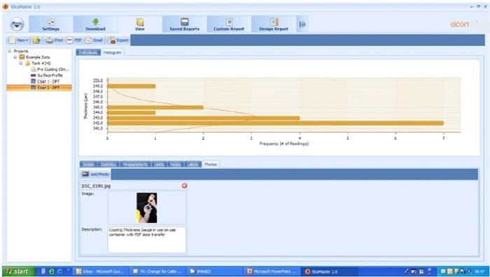
Screen shot of the Data Management Software Showing a Dry Film Thickness Batch with a Photograph
Once transferred, the data from the gauge can be managed utilizing the functions of the data management software. The batch data can be dragged and dropped in to a project folder. The individual readings can be viewed along with the statistics. Any limits imported from the gauge can be viewed and edited if required. Histograms, run charts and pie charts are calculated and can be displayed using the folder tags and notes can be added for clarity.
A simple to use report designer tool allows measurements to be added to images of the component by location. Measurements and statistical information can be placed in scanned document formats and data can be combined either as batches from the same gauge or by combining measurements from different gauge type in to a single report. For example, profile height and salt contamination measurements taken after blasting can be combined with climatic data collected during the coating application and dry film thickness values after the coating has cured to form a single comprehensive coating process report. The report can then be customized by adding company logos and other related information such as inspection procedures documents and specification information associated with the project.
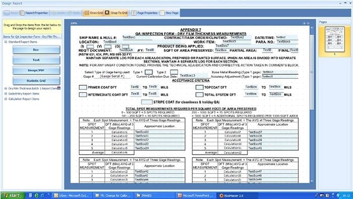
A Screen Shot Showing a Customized Report Format
When the report is completed it can be exported as a PDF format file either as an electronic file or by attaching the file to e-mail directly to the client.
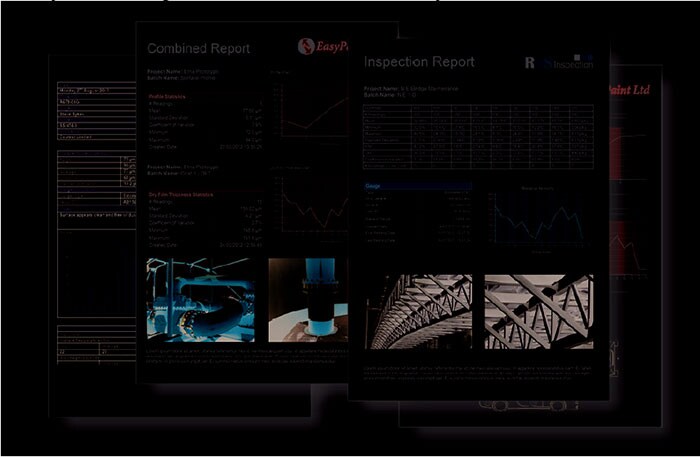
Some Examples of Customized Reports
MOBILE SOFTWARE
The PC operated software is also supported by Mobile software, which is designed for use on Android smart phones and tablets. This allows for live readings from a gauge to be stored directly on the phone and saved in batches or for batches of data to be transferred from the gauge to the mobile phone for immediate analysis on site.
This data can then be transferred from the phone in to the software operating on a PC or Laptop for further analysis, reporting, publication and archiving.
A method for sharing inspection data using mobile devices and ʻCloud Computingʼ is also available to speed communication of data and enable faster make decision making. The data management software enables simple and quick communication between gauges and either a computer running the software or mobile devices operating with Android systems and utilizing the Android Mobile program.
The Cloud allows data to be transferred, stored and accessed through an Internet providerʼs hardware, without the need for a local computer. There are a number of providers, e.g. Dropbox, Amazon Cloud Drive, Google Drive, Skydrive, etc. Any of these services can be accessed using personal computers and mobile Internet-capable devices.
Imagine an Inspector working at a remote site with no access to a computer network, or a number of inspectors working at different places on a large site or even on different sites, all needing to quickly communicate data to a central point. It would even be practical for several inspectors at several sites in different countries with a client in yet
another country to communicate quickly and simply using the cloud drive as a commonly accessed database resource.
The inspection measurements are taken on the structure and stored in the memory of the gauge. These readings can then be transferred from the gauge to any Smart phone or tablet using Android via the Bluetooth® communications and using the Android-based Mobile software. This data can be stored in the Cloud. The specific Cloud drive can then be accessed by any other authorized device, in any country on any continent, to share the information, quickly, accurately and at a low cost.
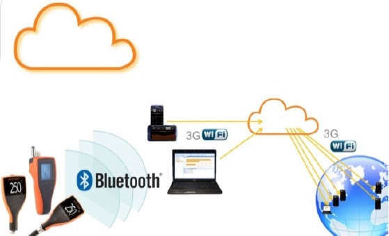
A Schematic Representation of Inspection Communication via “The Cloud”
Using these techniques allows inspection information to be shared instantly and therefore reporting time and delay costs are greatly reduced. Decision making, based on good quality information can be timely and accurate, particularly when re-working is indicated. At the end of a coating process, approval for the next stage can be quickly made, even when the client is at the other side of the world.
CONCLUSIONS
Speed of measurement is a vital aspect of the inspection of protective coatings particularly when large structures are involved. Clients want both evidence that the inspection has been carried out and timely information on which decisions can be based, particularly when reworking of the coating may be required.
It has been said that time recording and reporting on inspection processes is less productive than time spent actually inspecting. Therefore increasing the rate of data collection leads to improve productivity.
Recent developments in the design of coating thickness gauges have made it possible to both speed up the rate at which accurate measurements can be collected and to also speed up the communication of the resulting information to colleagues and clients alike.
The new probes with their patented gauge firmware support have a reading rate in excess of 140 readings per minute and the modern gauges have memory for up to 150,000 readings, making it possible for large structures to be measured and recorded up to 40% more quickly than with more traditional approaches.
Related Product(s)
Download Full PDF |