|
|
|
|
Measuring and Display Modes
| 
Measurement Modes Explained
")
|
ddd
|
Pulse - Echo Mode (PE)
The normal display mode, measures the total thickness from the base of the transducer probe to the material density boundary (typically the back wall). Ideal for pit and flaw detection.
|
|
|
|
|
:")
|
|
Pulse - Echo Temp Comp Mode (PETP):
Similar to the PE mode, PETP takes into account and compensates for the variations in measurement caused by temperature variations.
|
|
|
|
|
:")
|
|
Echo - Echo Mode (EE):
Also known as the ThruPaint™ Mode, EE ignores the·coating thickness, displaying the material thickness from the top surface of the material to the material density boundary.
|
|
|
|
|
:")
|
|
Echo - Echo Verify Mode (EEV):
The echo-echo verify mode measures by comparing the values between 3 reflections and is mainly used to eliminate errors from surface coatings and to make measurements in multiple layered materials.
|
|
|
|
|
:")
|
|
Coating Only Mode (CT):
Displays the thickness of the coating applied to the material.
|
|
|
|
|
:")
|
|
Pulse - Echo Coating Mode (PECT):
Displays both the material thickness (PE) and the coating thickness (CT) at the same time.
|
|
|
|
|

|
|
AWS
The American Weld Standard function provides automatic defect sizing in accordance with AWS D1.1 structural welding code. (Flaw Mode)
|
|
|
|
|

|
|
TRIG
TRIG enabling location of flaws in both surface distance and depth. Trigonometric display of beam path, depth, surface distance, and curved surface correction.
Used with angle beam transducers. (Flaw Mode)
|
|
|
|
|

|
|
TCG
Time corrected gain increases gain as time increases, in order to achieve an over all level of sensitivity for the same flaw/reflector at different distances. (Flaw Mode)
|
|
|
|
|

|
|
DAC
Distance amplitude correction for the creation of DAC curves which are used to inform the operator of the size of any given flaw at any depth. (Flaw Mode)
|
|
|
|
|
|
|
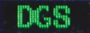
DGS/AVG
Allows automatic defect sizing from a single reference defect. (Flaw Mode)
|
|
|
|
|

|
|
Zero Crossing
The gate detects the flank of the pulse, but the measurement is taken at the next crossing of the x axis. This is the most common type of detect in ultrasonic measurement. (Flaw Mode)
|
|
|
|
|

|
|
Flank
The gate is triggered by the flank (or side) of the pulse on the graph and the measurement taken at this exact point. (Flaw Mode)
|
|
|
|
|

|
|
Peak
The gate is triggered by the intersection with the A-scan pulse and the detection is taken from the next peak in the signal (when it stops rising and starts falling). (Flaw Mode)
|
Display Modes Explained
|
|
|
|

|
|
Material Thickness Digits Display:
The standard display on all models, this displays the numerical thickness value in either millimetres (MM)or inches (IN).
|
|
|
|
|

|
dddd
|
Scan Bar Display:
A linear graphic display which allows users to graphically monitor changes in thickness readings. As the scale range can be adjusted by the user, this display is ideal for observing tiny variations in material thicknesses.
|
|
|
|
|

|
|
B-Scan Display:
A time based cross sectional 2D block view of the thickness provides a graphical view of the material thickness - ideal for relative depth analysis.
|
|
|
|
|
")
|
|
A-Scan Display; Full Wave (RF):
The A-Scan display shows the sine wave created by the reflected sound, or oscillation, from the material being measured. In RF mode the full wave form is displayed.
|
|
|
|
|
")
|
|
A-Scan Display; Rectified (+ or -):
Users can select to view either the positive or the negative cycle of the full waveform (RF). This rectified(RECT) display shows the amplitude of the echo versus the transit time.
|
|
|
|
|

|
|
Flaw Mode:
Available on the CG100ABDL+ & FD700+ series, this mode enables inspectors to locate porosity, defects, inclusions and cracks in a variety of test materials.The sound wave is introduced into the test material at a specific angle, and converted from a longitudinal wave into a shear wave.The introduction at specific angles enables inspectorsto steer the sound wave in a specific direction according to the position and location of specific types of defects.
|
|
|
|
|
|
|