 Author: John Fletcher, Technical Support Manager
Related Product(s)>>
>>Download Full PDF
ABSTRACT
A new software system has been developed to allow a plan to be created for the inspection tasks associated with the coating processes for a steel structure.
This system uses a coatings library to create the coating systems that are to be applied to various user-defined zones of the structure. These zones are identified on a schematic drawing of the structure and then the coating systems and inspection regimes that are required can be associated with these zones.
Inspection tasks are then planned and scheduled using a register of inspectors and the outcomes of the inspection tasks are recorded electronically so that the data to compile final report on the coating processes is collected in a managed way.
This paper describes the structure of the software and illustrates how inspection data is transferred electronically to the system using both wireless gauge technology and visual comparison systems. Examples of actual inspection tasks will be presented to illustrate how the system is used.
INTRODUCTION
As coating materials increase in cost and the maintenance coats for steel structures increase, the effectiveness of corrosion protection by coating becomes more critical both for new build and in service. It has been demonstrated on many occasions that good quality coatings require a rigorous inspection regime to ensure that the coatings are applied to correctly prepared surfaces under correct climatic conditions with the specified film thickness.
Ensuring that coating inspection tasks have been carried out correctly requires that records be maintained and that they be accessible for auditing and for review in the future when re-coating is required.
Many coating inspection tasks such as profile height measurement, temperature and humidity measurement and dry film thickness measurement can be carried out using electronic gauges that have the capability to store and upload readings from internal memory. However, there are some inspection tasks that require either visual assessment or measurement using gauges that do not have data output capability.
The quantity of records to fully document even a relatively simple structure indicates that a computer software system is desirable.
This paper discusses some of the issues raised by the planning and recording of inspection tasks using a new-build marine coating task as an example. The technique can also be applied to land-based structures for both new build and maintenance coatings.
THE PROBLEM
In order to deliver an anti-corrosion coating that is fit for purpose the application process must be controlled. The substrate must be correctly prepared and minimum levels of surface cleanliness and profile achieved. The coating process must result in the specified thickness of coating being applied under acceptable atmospheric conditions. Each of these requirements calls for several testing methods to be applied and the type of coating often dictates the level of performance required for test in each of these processes.
For example, coating manufactures recommend nominal dry film thickness values for which the properties of their coating apply, such as adhesion. In some cases maximum thickness values should not be exceeded to prevent cracking and other failure phenomena.
This means that a record of the specified coating and the coating system is essential when preparing and carrying out inspections.
In order to demonstrate the quantity of information that has to be managed for a project the following calculation has been made and is based on the general requirement for painting the ballast tanks on a new build a ship. Similar calculations can be made for other types of steel structures.
The typical dimensions of a Very Large Crude Carrier (VLCC) arei:
| Length: | 470m(1,542ft) |
| Draft: | 20m(66ft) |
| Beam: | 60m(197ft) |
The total ballast tank coating area onboard a VLCC is approximately 300,000m2 (greater than 3,000,000ft2)ii.
Using the SSPC PA2 standard for coating thickness measurementiii, each flat area requires five spot readings - each the average of three readings per 10m2 or 100ft2
Taking into account the typical dimensions of a VLCC, the outer surface area of the ship is approximately 52,000m2 (558,000 ft2). If we assume that there are two coating layers applied, inspecting the vessel’s outer surfaces alone, under SSPC PA2, would require 156,000 individual coating thickness readings to be taken and recorded. This increases to 167,400 when using the Imperial unit of area measurement within SSPC PA2. This does not take into account any complex areas or the superstructure itself.
According to the IMO regulationsiv the following dry film thickness verification regime is to be adopted for the inspection of ballast tanks:
- one gauge reading per 5m,sup>2 (54ft2) on flat surface areas;
- one gauge reading at 2 or 3m (6.5 – 10 ft) intervals and as close as possible to tank boundaries, but not further than 15mm (0.6 inch) from edges of tank boundaries;
- around openings one gauge reading from each side of the opening;
- additional spot checks are to be taken to verify coating thickness for any area considered necessary by the coating inspector.
Additional inspection requirements are listed for longitudinal and transverse stiffener members, primary support members and complex areas (specifically large brackets of primary support members).
Using the lowest possible estimate, this indicates that a minimum of 300,000 coating thickness readings which must be taken and recorded to meet the obligation of the IMO PSPC for Salt Water Ballast Tanks regulation. So the imperative for coating thickness measurement is, in essence, is similar to the number of readings you are required to take when using SSPC PA2 for the outer hull surfaces alone. This of course does not take into account any internal surfaces, cargo holds, fixtures and fitting or any complex areas under consideration.
The IMO regulation does not stop at coating thickness, it also requires the inspection of surface profile and cleanliness, weld condition, coating damage together with the recording of temperature, relative humidity, dewpoint and weather conditions, where appropriate, during the application process and for the paint cure, at each stage of the build process. Cumulatively, this is a very significant quantity of data.
Not all coating inspection processes for ballast tank coatings have measurements associated with them. Some inspection types rely on the judgement of the inspector in respect of a standard, for example the rust cleanliness assessment after blasting is by reference to the Swedish Rust Standard, EN ISO 8501. Records of this type of inspection require the inspector’s signature for verification and trace-ability.
Taken all together, the quantity and type of information that needs to be collected to satisfy the requirement to produce a coating technical file for the ballast tank coatings is extensive. The further requirement to be able to track the individual ballast tank areas of the ship and the reworks that may required to achieve satisfactory coatings means that a document archiving and retrieval method is applied.
THE NEED
In planning the coating process inspection tasks it is necessary to consider how the inspections will be carried out. For some inspection tasks readings are taken using gauges, some of which have memory and data output and some of which just display a value. For other inspection types a visual comparison with a standard or assessment to a written guideline is made. Several inspection processes rely on the knowledge and training of the inspector and are recorded on a pass/fail basis.
Computer-based recording systems have to be able to accommodate all of these options. For a typical anti-corrosion coating system the inspection regime may be as follows:
- Pre-preparation Inspection:
- Initial steel surface condition – ISO 8501
- Edges
- Welds
- Post-preparation Inspection:
- Rust removal – ISO 8501
- Dust removal – ISO 8502-3
- Surface Contamination – Soluble Salts ISO 8502-6 and ISO 8502-6
- Surface Contamination – Oil and Grease
- Climatic Conditions
- Relative Humidity
- Air Temperature
- Surface Temperature
- Dewpoint Temperature
- Coating Inspection:
- Wet film thickness
- Cure Conditions
- Relative Humidity
- Air Temperature
- Surface Temperature
- Dry Film Thickness
- Post Coating Inspection:
- Adhesion
- Damage - Visual Appearance
- Porosity
- Appearance
The following case study applies to the management of inspection tasks for painting ballast tanks but the principles can be applied to the coating of a range of structures.
THE SOLUTION
In order to collate all the information and records so that a coating technical file can be prepared easily and navigated for audit purposes, the use of a computer database is indicated. There are several additional advantages that arise from this approach, including direct communication with the database where measurement data is acquired using an electronic gauge with a data output feature, the ability to store technical datasheets for the coating materials for reference, the opportunity to identify the location of the ballast tanks on a drawing of the ship for convenience and the means of associating photographic images with the data.
A software system has been developed to provide a framework for the planning and recording of coating inspection tasks associated with a particular ship by name. The software has 7 sections to aid the planning and creation of inspection tasks, with a further 5 operational features for managing the inspection tasks and creating the coating technical files.
Once created, the inspection tasks can be scheduled and allocated to a specific inspector and the system can implement this process using Personal Digital Assistants (PDA’s) so that the work can be allocated and carried out remotely from the computer for maximum efficiency.
The seven sections leading to the creation and recording of inspection tasks are as follows:
- Coating Library – creation and maintenance of the approved coatings by supplier
- Coating System – creation of the coating systems in use for different areas of the ship
- Register of Inspectors – details of all the inspectors allocated to the ship and their access permissions
- Inspection Regimes – individual inspection points that can be grouped together as required.
- Ship Structure – details of the ship with drawings and ship parts linked to the coatings
- Inspection Tasks – individual inspection tasks with record of completed tasks and links to rework
- Daily Log – additional inspection information recorded by the system administrator on a daily basis
The five operational features of the software are:
- Inspection PDAs – manages the individual PDA’s allocated to the inspectors
- Outstanding PDA Inspections – ad hoc inspection task records that require consolidation in the overall inspection plan
- Coatings Technical File – the function that validates and creates the coating technical files for either the ballast tanks (IMO regulations) or the rest of the ship
- Status – automatic record of software activity
- Change Log – automatic record of activity by ship structure or by inspector
OPERATION OF THE SOFTWARE
To populate the relational database with the information required for the Coatings Technical File, key data is required for the different sections. The starting point is the coating library where all the coatings approved for use on the ship and particularly for the ballast tanks are entered. Each coating is entered and filed by Manufacturer, with the software creating unique identification for the individual record. Key information, such as manufacturer, product name and product ID together with mandatory detail such as nominal wet film and dry film thickness, nominal profile height, and nominal climatic conditions (air temperature, surface temperature and humidity) as detailed in the manufacturers technical datasheets, is entered here.
The coating record has fields for notes and for the association of electronic files such as data sheets and reference documents and, where appropriate, a coating approval number.
These individual coating record are issued and these issues can be updated as the ship build proceeds, if for example, the specification of a particular coating is changed, the change can be recorded and the record up issued. The software will then track tasks carried out using the first issue of the coating and the more recent tasks carried out using the up-issued coating material.

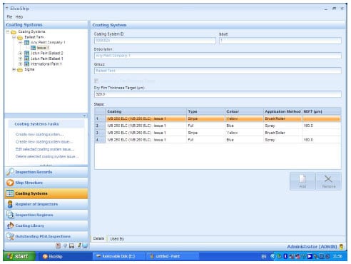
Figure 1 - An Example of the Coatings Systems Screen
Showing a typical coating system for ballast tanks
The coatings are then arranged as systems using the Coating System function. Each coating system that is created has a unique identification and is stored by description and group. The group may be a ballast tank coating system, for example. The coating steps are then specified and this may be a stripe coat and two full coats using a particular coating with alternating colors to aid inspection.
The Register of Inspectors creates an individual inspector’s record together with the inspector’s account type to set the access permissions to the software. An individual inspector can be linked to a contractor and the record is password protected so that data submitted by the inspector has to be confirmed by use of the password. The register page has fields for an electronic signature to record the signature that will be used on the PDA to complete inspection tasks and file space for a photograph and a copy of the inspector’s certificate. There is also a non-mandatory field to record the certificate expiry date to track the validity of an inspector’s status over time. Inspectors can have their status changed and can become inactive if they are not able to work on an inspection plan for some reason, e.g. ill health.
The Inspection Regimes function is used to group inspection requirements together for maximum efficiency. For example, if a surface were being inspected for profile then it would be sensible to consider inspecting for rust removal, dust, and oil and grease contamination at the same time. By grouping the individual inspections as a regime the system will combine these tasks, while leaving the possibility of planning a single task if a rework is required, for example.
Having set up the coatings library, the coating system and the register of inspectors the task of recording the ship structure and the ship parts needs to be carried out to provide a basis for planning the inspection tasks.
The Ship Structure allows a new ship to be created with an automatic and unique ID together with the relevant detail such as hull number/IMO number, the customer’s name and the ships name. Non-mandatory information such as the contract date, the keel-laying date, the planned launch and delivery dates can be entered in the appropriate fields. Mandatory information for creating of a new ship includes the gross tonnage, the dead weight, the length (OA and BP), the beam, the draft and the depth.
There are fields within the Ship Structure records for general comments, general ship documents, coating technical file audits and coating technical file approvals documents.

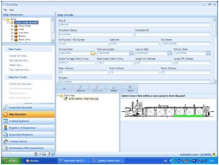
Figure 2 - An Example of the Ship Structure Screen
Showing the ballast tank areas marked in green as ship parts
Drawings in JPG format can be associated with the Ship Structure record and the areas of the ship can be highlighted as part of the ship part definition. Each Ship Part is created within the build structure of shop primer, units, unit joins, blocks, block joins, super blocks, erection joins with a special file for ballast tanks. The individual Ship Parts can be allocated to a preferred inspector and the coating system for the surfaces in the Ship Part defined with the location of the Ships Part.
At this point, selecting the Ships Part and Inspection Records allows a new Inspection Record to be created for the Ships Part and the selected surfaces. This record then becomes an inspection task that can be schedules as part of the overall plan or completed either directly on the computer running The software or more likely by e-mailing or transferring the task to an Inspector’s PDA for completion at the location of the work. By using the e-mail option the Inspector can be given work and respond with completed tasks without visiting the planning office.
The Daily Log is initiated for any day when an inspection task is completed. If the Daily Log is opened a list of the completed inspections can be viewed and additional comments can be added with support files, such as photographs, for the user to confirm by password and electronic signature.

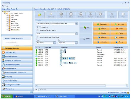
Figure 3 - An Example of the Inspection Records Screen
Showing completed inspection tasks
THE INSPECTION PROCESS
To maximize the flexibility of the database, inspections can be recorded using a hard copy printout of the inspection task or by transferring the task electronically to a PDA or by completing the selected task on the computer. However, it is envisaged that the most convenient and efficient way in which inspections can be completed is by transferring the chosen tasks to a PDA allocated to the inspector chosen for the inspection task. The PDA operates using an associated program running under Microsoft Windows Mobile on any suitable PDA.

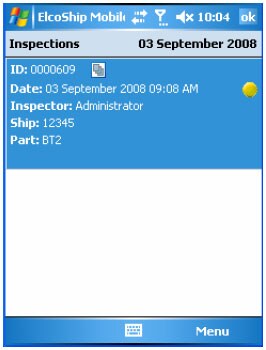
Figure 4 – An Example of the PDA Screen
Showing an Inspection Task ready to be opened for completion
The PDA user has the opportunity to decline a particular task with a reason if the task cannot be completed as intended. The software administrator can then re-allocate the inspection task to another member of the team.
If an inspection task is completed using a hard-copy the finished document has to be scanned to create an electronic file that can be associated with the inspection task for the administrator to complete the task and create a record for that inspection.
However, tasks completed using the PDA can transfer the record to the computer along with any readings from electronic gauges and if appropriate photographs of the area being inspected. This information is then stored in the relational database and the status of the task is updated within the software. Gauges with Bluetooth® enabled data transfer can upload a batch of readings associated with an inspection record so that the task is automatically completed the next time the PDA next communicates with the program.
The inspection tasks are color coded, using blue for tasks that are ready for completion, yellow for active tasks, green for successfully completed tasks and red for failed inspections. Green tasks can also be marked as tasks passed on concession, the green marker contains a white letter C, or passed after rework, in which case the marker contains a white letter R.
CONCLUSIONS
To ensure that corrosion protection coatings meet their specified service life, it is essential to confirm that the coating process has been carried out under optimum conditions and that the inspection processes are effective. This in turn requires adequate testing, measurement and recording to enable a useful project report to be created providing support for the life of the structure, during maintenance and repair.
Protective coating processes are complex and there are many inspection tasks at the various stages, resulting in a large quantity of inspection information to be managed. This volume of data means that a direct computer-based software solution is required. This will provide improved accuracy, reduce costs, time saving, improve data retrieval and simplified audit and review procedures.
The use of a computer-based solution also means that advantage can be taken of direct communication between gauges and computers either by cable or by wireless links, such as Bluetooth®. However, as inspections based on measurements are not the only requirement, the scope of the software must included the inspection tasks that require the assessment against a visual standard or the skill and experience of the inspector on a pass/fail basis. This is best achieved by utilizing the Personal Digital Assistant (PDA) to provide an electronic link between the software planning and recording system and the inspector on site.
Although the computer software used to illustrate this paper is designed for ballast tank coatings on ships it is easy to see how the same system with different terminology could be used for other steel structures such as bridges, tanks, pipelines and rigs.
REFERENCES
i www.wikipedia.com; March 2008
ii J. Eliasson & D Rauta; The New IMO Ballast Tank Coating Standard – What Does It Mean?
Journal for Protective Coatings & Linings, May 2007
iii SSPC-PA 2, Measurement of Dry Coating Thickness With Magnetic Gages
iv The International Maritime Organisation (IMO) regulation for the Performance Standard for Protective Coatings (PSPC) for Salt Water
Ballast Tanks, Resolutions MSC.215 (82) & MSC.215 (84)
Related Product(s)
Download Full PDF |